Flag 2D
The Flag 2D problem from Turek and Hron [1] is used to benchmark PVade.
Geometry Definition
The 2D flag problem consists of a channel flow in which the fluid interacts with a structure defined by a rigid cylinder (flagpole) and an attached flexible beam (flag), where a strong oscillatory flapping emerges over time due to the fluid-structure interaction. We present the results of this FSI benchmark below. The geometry of the problem is described in the Figure below.
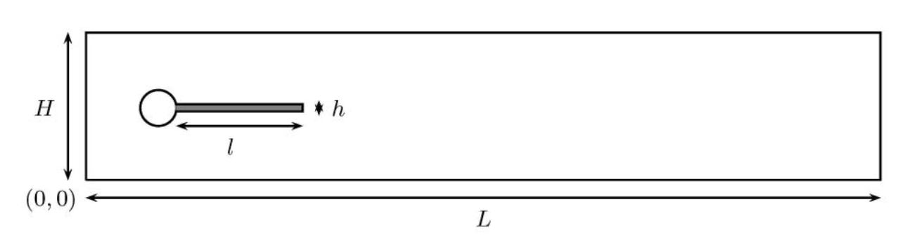
where:
L is the length of the domain H is the height of the domain l is the lentgh of the flag h is the thickness of the flag

C is the center of the circle r is the radius of the circle A is the measurment point for benchmarking
For the upcoming benchmarks the following values are used:
par. dim. |
Value |
|---|---|
\(H [m]\) |
0.41 |
\(L [m]\) |
2.5 |
\(h [m]\) |
0.02 |
\(l [m]\) |
0.35 |
\(C\) |
(0.2,0.2) |
\(A\) |
(0.6,0.2) |
\(r [m]\) |
0.05 |
Structural Benchmarking
The Benchmarking of the structural solver is follows the CSM3 example in Turek and Hron [1].
In CSM3, the structural tests are computed only for the elastic beam (without the surrounding fluid) adding the gravitational force only on the structural part, g = (0, g) [ m ]. The CSM3 test is computed as a time dependent case starting from the undeformed configuration
The Parameters used for the benchmarking are defined below
par. dim. |
Value |
|---|---|
\(\rho_0 [10^3 \frac{kg}{m^3}]\) |
1 |
\(\nu\) |
0.4 |
\(\mu [10^6 \frac{kg}{ms^3}]\) |
0.5 |
ndof |
ux of A [×10−3] |
uy of A [×10−3] |
|
|---|---|---|---|
PVADE |
6522 |
-15.368 ± 15.369 [1.0956] |
-65.624 ± 67.515 [1.0956] |
CSM3 |
6468 |
−14.279 ± 14.280 [1.0995] |
−63.541 ± 65.094 [1.0995] |
When we plot the “x” and “y” displacement of the point A versus time we obtain the following

FSI Benchmarking
In this example, we will solve a 2D flag simulation known as FSI2 using the PVade code. This example uses a custom domain creation file but otherwise sets boundary conditions and defines the key geometric quantities presented above using standard PVade definitions (instances where these definitions might be unclear when adopting our standard PV naming conventions are marked with comments in the input file). The input file used for this example is the following:
general:
  geometry_module: flag2d
  output_dir: output/flag2d
  mesh_only: False
  structural_analysis: true
  fluid_analysis: true
domain:
  x_min: 0.0
  x_max: 2.5
  y_min: 0.0
  y_max: 0.41
  l_char: .002
pv_array:
  panel_chord: 0.35 # Sets the length of the flag (starts outside circle radius)
  # panel_chord: 0.0 # Sets the length of the flag (starts outside circle radius)
  panel_span: 0.05 # Sets the radius of the flag pole
  panel_thickness: 0.01 # Sets the thickness of the flag
  span_rows: 1
  stream_rows: 1
solver:
  dt: 0.005
  t_final: 10.0
  solver1_ksp: gmres
  solver2_ksp: gmres
  solver3_ksp: gmres
  solver4_ksp: gmres
  solver1_pc: hypre
  solver2_pc: hypre
  solver3_pc: hypre
  solver4_pc: hypre
  save_text_interval: 0.005
  save_xdmf_interval: 0.005
fluid:
  u_ref: 1.0 # 0.2 1.0 2.0
  rho: 1000.0 # 0.2 1.0 2.0
  nu: 0.001 # Establish re = 20 with diam = 0.1 and u = u_ref
  dpdx: 0.0
  turbulence_model: null
  periodic: false
  bc_y_max: noslip # slip noslip free
  bc_y_min: noslip # slip noslip free
  # warm_up_time: 0.25 # slip noslip free
structure:
  dt : 0.005
  rho : 10000.0
  poissons_ratio: 0.4
  elasticity_modulus: 1.4e+06
  body_force_x: 0
  body_force_y: 0
  body_force_z: 0 #100
  bc_list: ["left"]
  motor_connection: False
  tube_connection: False
This example is executed using:
python --input $PVade/input/flag2d.yaml
PVade start by generating the mesh for the computational domain. In this case we are generating 2 meshes, 1 for the fluid and 1 for the structure, which match at the boundary.
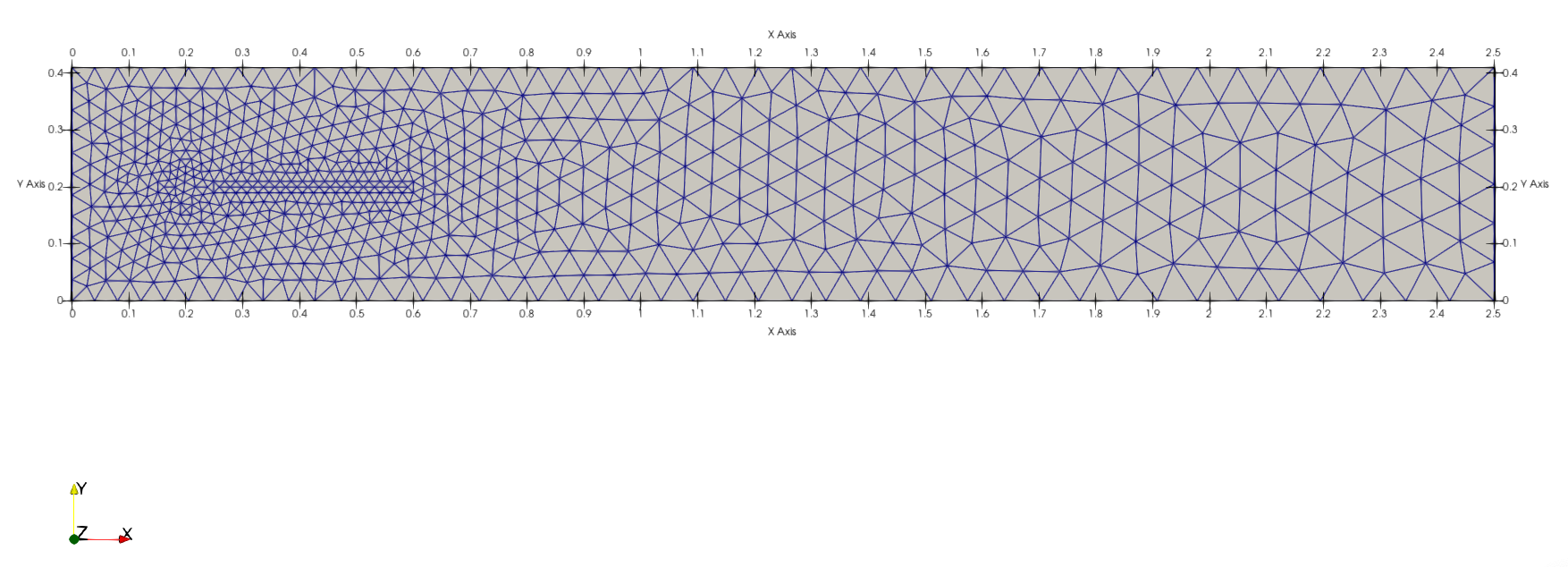
The full computational Domain
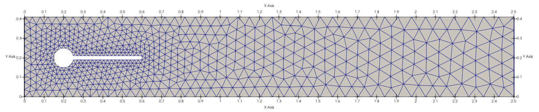
The CFD domain
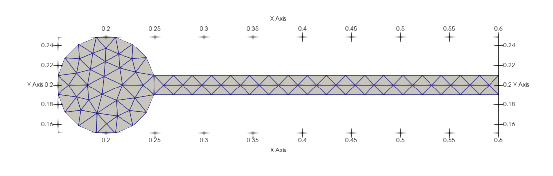
The structural domain